14 KiB
| fontfamily | fontsize | geometry |
|---|---|---|
| dejavu | 16pt | a4paper,margin=2cm |
MicroDexed Build Manual

Version 1.0 (June 2020)
Requirements
Making a TeensyMIDIAudio board is not very difficult, but you should consider the following:
- You should've soldered something before, preferably a small kit. Without some practice you will get problems with bad soldering joints. Errors like this are always very difficult to find if you have not worked properly. Instructions on how to solder and which tools to use can surely be found on the Internet.
- You need time! Someone with a lot of experience and practice can finish the whole kit in 2 hours. But if you don't take enough time, there is a high risk to fill something wrong or to create bad soldering joints.
- You need good tools. Good doesn't always mean expensive. But don't try to work with unsuitable tools, because it may also lead to problems.
Tools
- Soldering iron: It is best to use a temperature-controlled soldering iron or a station with about 40 watts of power. Never use soldering tips that are too large or a soldering iron with a large capacity.
- Soldering tin
- (Small) Side cutter
- "Helping hand" or heat resistant fastening material
- Stripping tool
- Hot air gun for shrinking tube
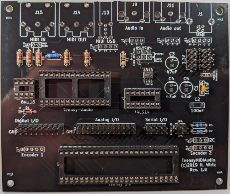
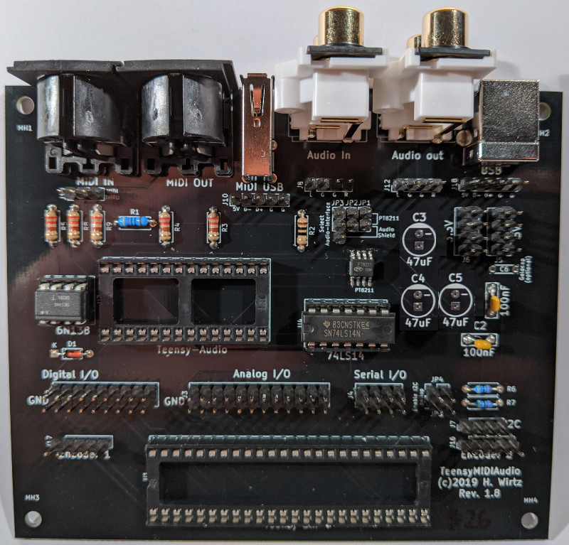
Build
The printed circuit board has numerous optional components that only need to be mounted in certain cases. This guide shows you all possible options and indicates whether steps are optional or recommended. All steps without further hints are necessary.
It is also possible to equip the board with a PT8211 I2S audio chip instead of the Teensy Audio Shield. This option is not shown here. If you want to use this option, please take a look at the schematic or ask directly via email or in the forum.
The build process is organized into several steps. Each step is on one page with pictures showing the relevant changes. It is good practise to take a short break after each step. For steps in which you have to solder very much (like the IC sockets) you should take breaks in between.
Be careful when soldering on the Teensy audio board! You should take care not to stay too long on one soldering point. Again, take breaks to let the soldering joints cool, so that the chip on the board will not be damaged.
If you are unsure or the manual is not precise enough or misleading, please ask by email or forum before doing something wrong!
Note: The photos show a mounted SMD component (type PT8211). This is not necessary and is not pre-assembled.
Kit completeness check
Included parts
- Resistors:
- R1 (470 Ohm)
- R3, R4, R5, R8, R9 (220 Ohm)
- R6, R7 (4.7 kOhm)
- Diodes
- D1 (1N4148)
- Capacitors
- C1 (100 nF)
- IC sockets
- U1 (2*24 pin)
- U2 (2*14 pin)
- U4 (2*8 pin)
- U5 (2*8 pin)
- IC's
- IC4 (74LS14 -> U4)
- IC5 (6N138 -> U5)
- Sockets
- J1 (USB-B socket)
- J13 (USB-A-socket (horizontal))
- J9, J11 (Stereo RCA socket (horizontal))
- J14, J15 (DIN-socket)
- Pin header
- J2, J3, J4, J5, J6 (double pin row)
- J7, J8, J10, J12, J16, J17, J18, J19 (single pin row)
- Jumpers
- JP3, JP4, JP5
- Additional Parts
- 2 Encoder
- 2 Encoder knobs
- 10 7cm jumper cables (open/female - for encoders)
- 1 LCD-display 16*2 lines
- 1 LCD cable (4 pin female/female)
- 1 Micro-USB adapter cable
- 1 Teensy-MIDI-Audio-PCB
- 11 7cm jumper cables (female/female - for audio and USB-host)
- 1 10cm heat-shrink tubing (for 10 * 1 cm for encoder cables)
External parts (not included in this kit)
- 1 Teensy-3.6 (or Teensy-3.5 with some limitations, Teensy-4.x will not work with this board!)
- 1 SD card 2-32GB
- 1 Teensy Audio Shield (SGTL5000, Rev. C, the Rev. D board for Teensy-4.x will not work!)
- 1 USB power supply
Assembling the kit
For the assembly of printed circuit boards you should always start with the flattest components and mount the higher components step by step. On the next pages you will find several steps for the parts in a recommended order.
- Diode and Resistors
- Capacitor
- IC sockets
- Double-row pin headers
- Single-row pin headers
- Sockets
- Solder the audio card
- Solder USB-Host pin header for the Teensy-3.6 (OPTIONAL)
- Solder the encoders
- Insert the ICs
- Insert the Teensy
- Connect USB-Host (OPTIONAL)
- Insert the audio card
- Connect audio card
- Prepare and insert SD card
- Connect encoders
- Connect LCD display
- Setting jumpers
- Test and trouble-shooting
Diode and Resistors
You need:
- Diode D1 (1N4148)
- Resistors
- R1 (470 Ohm / 470)
- R2 (10 Ohm / 10)
- R3 (220 Ohm / 220)
- R4 (220 Ohm / 220)
- R5 (220 Ohm / 220)
- R6 (4.7 kOhm / 4K7)
- R7 (4.7 kOhm / 4K7)
- R9 (220 Ohm / 220)
- R10 (220 Ohm / 220)
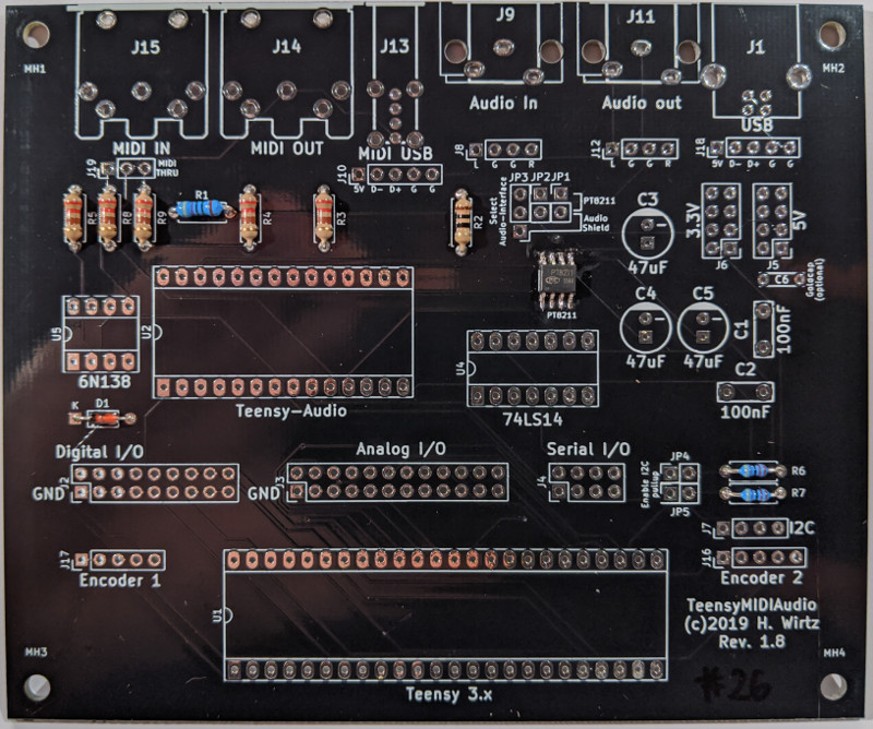
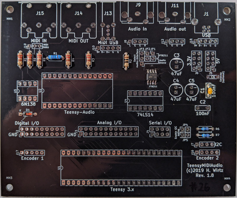
Capacitor
You need:
- Capacitor C1 (100 nF)
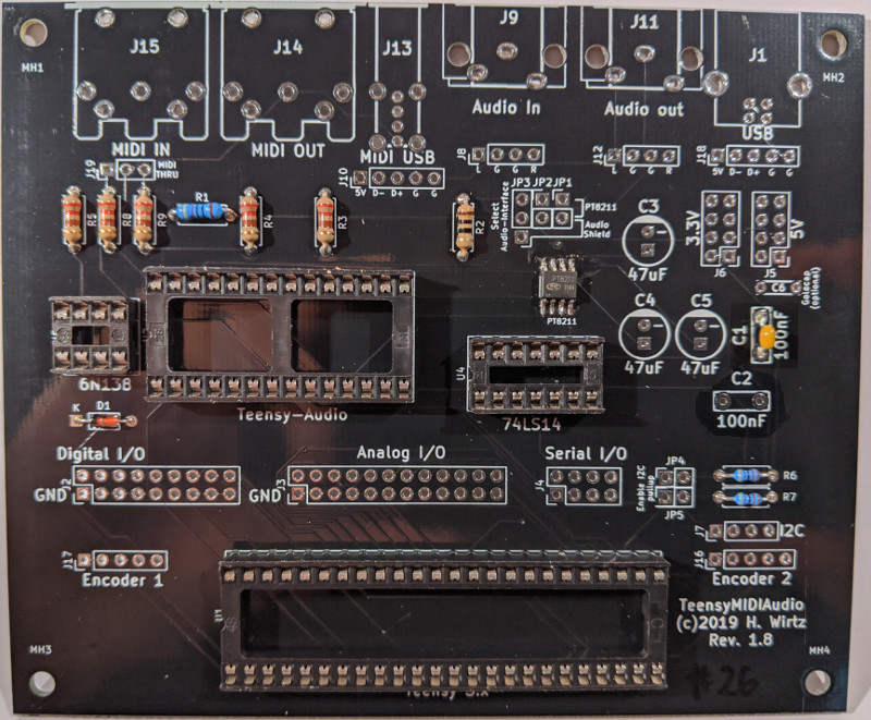
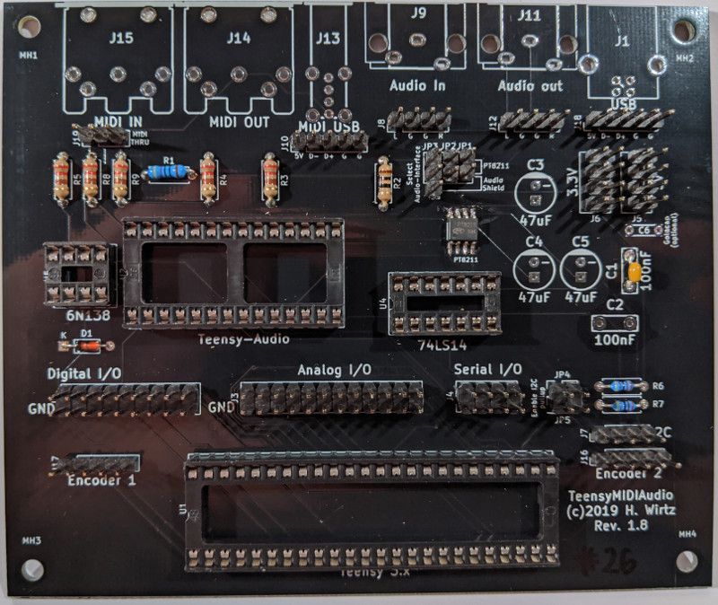
IC sockets
Note the mounting direction in the IC sockets: If the board is aligned like in the picture below, the notches of all IC-sockets must point to the left.
You need:
- U1 (2*24 pin)
- U2 (2*14 pin)
- U4 (2*8 pin)
- U5 (2*8 pin)
Double-row pin headers
You have to cut the needed number of pins from the long double-row-headers on your own. Only JP4 is needed, the rest are optional signals and ground pins if you want to extend the hardware by yourself. For more information take a look at the circuit diagram.
You need:
- JP4 (2 * 2 pin rows)
- J2 (9 * 2 pin rows) (OPTIONAL)
- J3 (12 * 2 pin rows) (OPTIONAL)
- J4 (4 * 2 pin rows) (OPTIONAL)
- J5 (4 * 2 pin rows) (OPTIONAL)
- J6 (4 * 2 pin rows) (OPTIONAL)
Single-row pin headers
You have to cut the needed number of pins from the long single-row-headers on your own. Only JP1/JP2/JP3/J7/J6/J17 are needed, but it is recommended to solder the remaining headers as well. For more information take a look at the circuit diagram.
You need:
- JP1 (2 * 1 pin row)
- JP2 (2 * 1 pin row)
- JP3 (3 * 1 pin row)
- J7 (4 * 1 pin row)
- J16 (5 * 1 pin row)
- J17 (5 * 1 pin row)
- J18 (5 * 1 pin row) (RECOMMENDED)
- J12 (4 * 1 pin row) (RECOMMENDED)
- J8 (4 * 1 pin row) (RECOMMENDED)
- J10 (5 * 1 pin row) (RECOMMENDED)
- J19 (3 * 1 pin row) (RECOMMENDED)
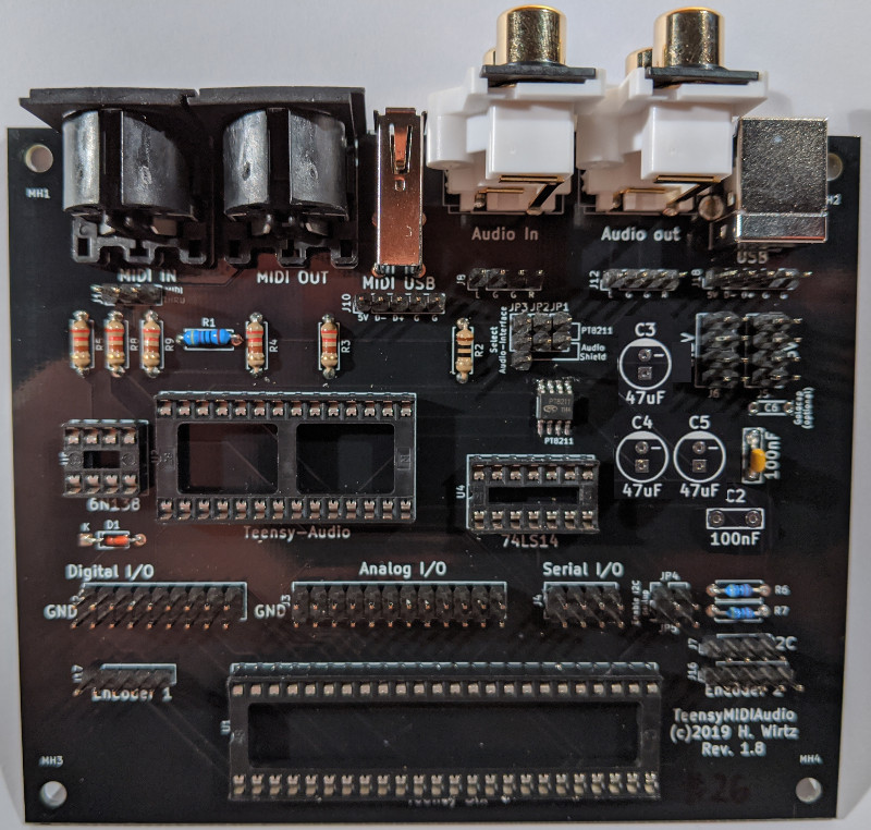
Sockets
Only J1/J11/J15 are needed, but it is recommended to solder the remaining sockets as well. For more information take a look at the circuit diagram.
You need:
- J1 (USB-B socket)
- J11 (Stereo RCA socket (horizontal))
- J15 (DIN-socket)
- J9 (Stereo RCA socket (horizontal)) (RECOMMENDED)
- J14 (DIN-socket) (RECOMMENDED)
- J13 (USB-A-socket (horizontal)) (RECOMMENDED)
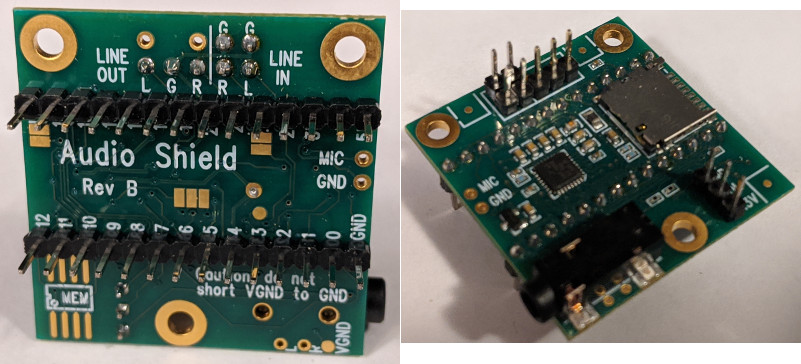
Solder the Teensy Audio Shield
You have to cut the needed number of pins from the long single- and the double-row-headers by yourself. The 2 * 2 pins are optional and only needed if you want to use the option for audio-input. The 3-pin-single-row header on the right picture (for GND/VOL/3.3V) is not needed.
Be careful not to overheat the onboard chip when soldering the headers. Take a small break after soldering every pin to let it cool down.
You need:
- Teensy Audio Shield (not included in the kit)
- 1 * 3 pin rows
- 2 * 14 pin single row
- 2 * 2 pin rows (OPTIONAL)
Solder USB-Host pin header for the Teensy-3.6 (OPTIONAL)
You have to cut the needed number of pins from the long single-row-headers by yourself.
Be careful not to overheat the onboard chips when soldering the header. Take a small break after soldering every pin to let it cool down.
You need:
- Teensy-3.6
- 1 * 5 pin rows
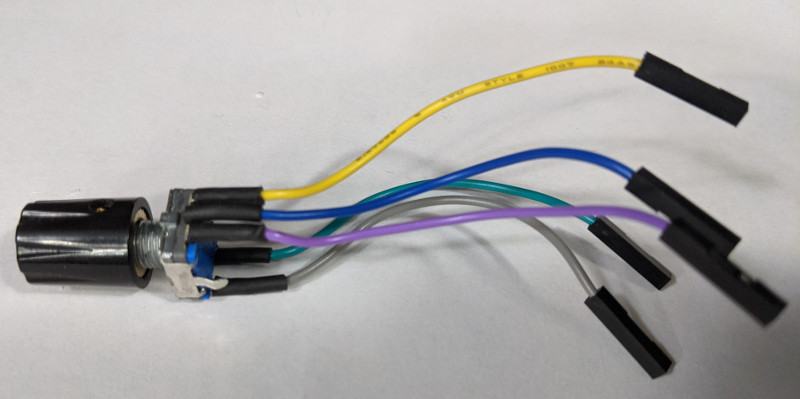
Solder the encoders
The kit contains 10 wires with open ends. These open ends must be stripped, tinned and soldered. You need 5 wires per encoder. To be on the safe side, heat shrinkable tubing should be put over the soldering joints. For this you have to cut 10 pieces out of the long shrink tube.
You need:
- 10 7cm wires (open/female)
- 2 encoders
- 2 encoder knobs (OPTIONAL)
- 10 pieces of 1 cm shrink tube
Insert the ICs
Note the direction in which the two ICs must be inserted: If the main PCB is aligned like in the picture below, the notches of both ICs must point to the left.
You need:
- IC4 (74LS14 -> U4)
- IC5 (6N138 -> U5)
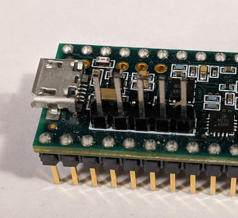
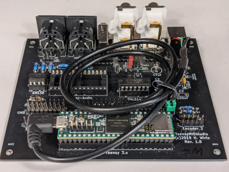
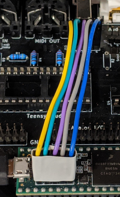
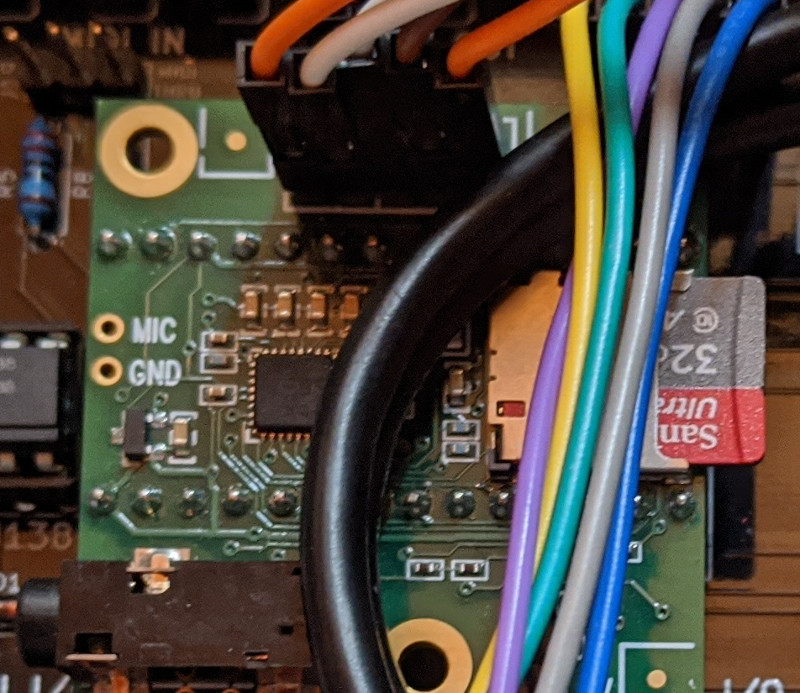
Insert the Teensy
Note the direction in which the Teensy must be inserted: If the main PCB is aligned like in the picture below, the SD card slot must point to the right. Also connect the USB adapter cable so that the thicker black end of the female connector is located to the right (like in the picture below).
You need:
- Teensy-3.x (not included in the kit)
- Angled USB micro adapter cable
Connect USB-Host (OPTIONAL)
Connect the USB-host pins of the Teensy-3.6 to the pin headers on the main PCB. The order is straight through as shown in the picture below.
You need:
- 5 7cm female/female wires
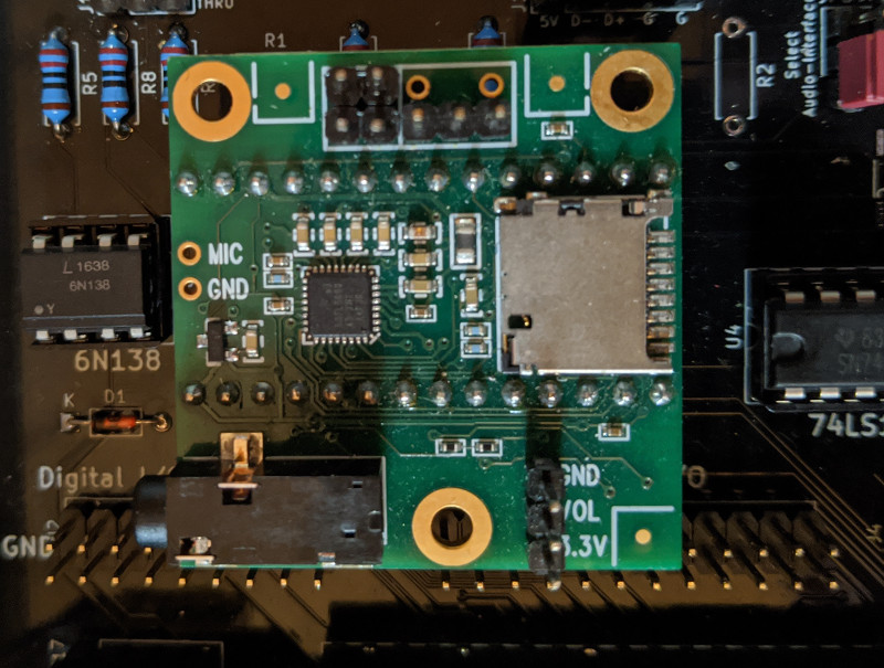
Insert the Audio Shield
Note the direction in which the Audio Shield must be inserted: If the main PCB is aligned like in the picture below, the SD card slot must point to the right.
You need:
- Teensy audio card (not included in the kit)
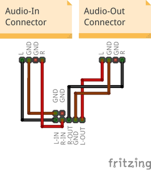
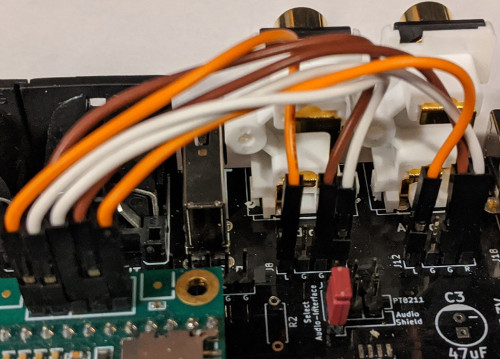
Connect Audio Shield
Connect the audio ports of the Audio Shield to the pin headers on the main PCB. You only need to connect the audio-out port, but it is recommended to also connect the audio-in port. For the wiring look at the wiring scheme below.
You need:
- 3 7cm female/female wires for audio-out
- 3 7cm female/female wires for audio-in (RECOMMENDED)
Prepare and insert SD card
Format the SD card as FAT32 and copy the contents of the directory addon from the MicroDexed directory to the SD card. You can also install your own SYSEX files (or load them directly onto the MicroDexed later). It is important to keep the directory structure: For each bank there is a directory with the bank number as name.
The SD card can be inserted into the Teensy or the audio card.
You need:
- SD card (not included in the kit)
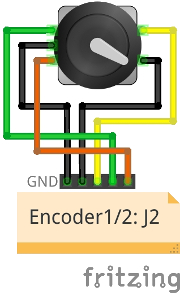
Connect encoders
Connect the pre-soldered encoders to the pin headers on the main PCB. The order is shown in the diagram below.
You need:
- 2 pre-soldered encoders
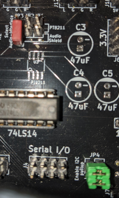
Setting jumpers
The jumpers are needed to decide which kind of I2S sound chip you want to use and to enable the I2C pullup resistors. To enable them close JP4 and JP5. Then set JP3 to the down position (as seen in the picture below) and leave JP1 and JP2 open.
You need:
- 3 jumpers
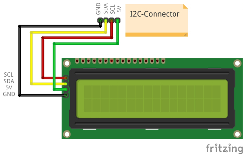
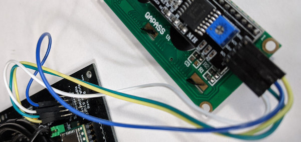
Connect LCD display
Connect the LCD to the pin headers on the main PCB. The order is shown in the diagram below.
You need:
- LCD display
- 4 10cm female/female wires
Test and trouble-shooting
Now you are ready for the first test. But before, please check again the following:
- orientation of the ICs
- orientation of the Teensy
- orientation of the Audio Shield
- SD card is inserted
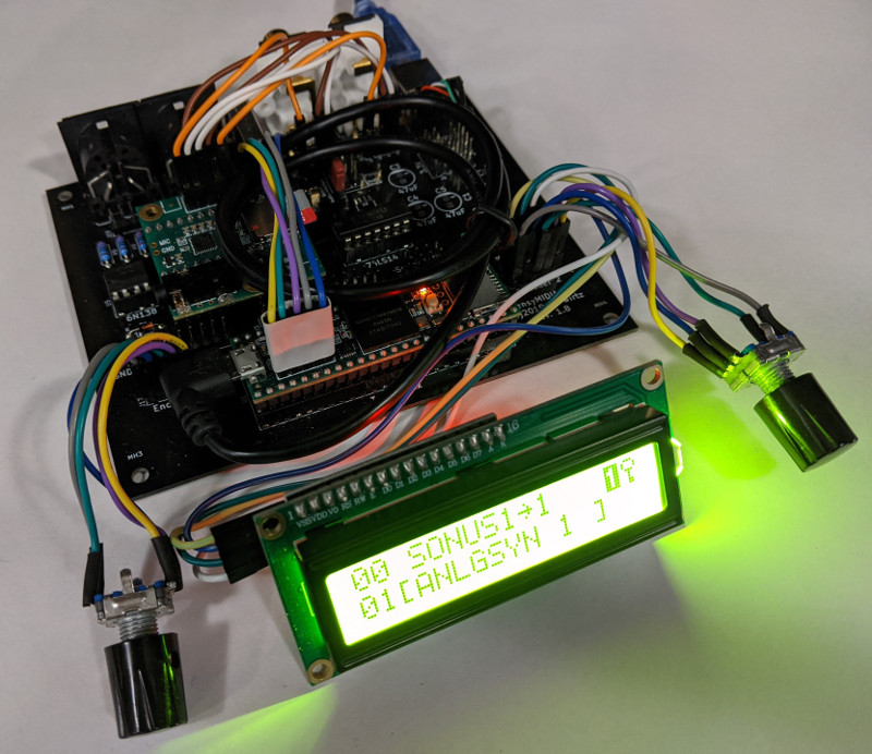
Now you can try to power up your kit. If everything works, the display should show a short text during the boot process. After that you you should see the bank/voice selection.
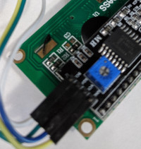
Problem: Nothing is visible on the LCD
This can happen if the contrast of the LCD display is not set correctly. To adjust it you can (carefully) adjust the contrast with a small screwdriver using the blue potentiometer on the back of the LCD display while power is connected.
Problem: The screen hangs on the boot message
This may be due to problems with the SD card? The synth will only work if the SD card works correctly. If the SD card is not recognized, the system will stop. Try to format it again as FAT32 and copy the preset data or try another SD card.
Problem: The encoders are reversed
The lines on the encoder (on the three-pin side, the lines on the right and left) have been connected to the headers in reverse order. Exchange them crosswise on the main board.
Problem: The encoder buttons don't work
Check if the two wires from the encoder (from the two pin side) are connected to the correct header on the main board.
It is also possible that the potentiometer knobs are mounted too close to the encoder. Loosen the screw in the potentiometer knob and push the knob a bit further away from the case. You can also remove it first and try to push the buttons without the knobs.
Problem: There is no sound
First check your MIDI wiring. Are you getting signals? The LCD should show a note symbol or a box symbol under the inverse 1 when you press a key. If not, no MIDI signals are detected and no sound is generated.
Did you reset the EEPROM? You may need to reset the EEPROM after each time you flashed the firmware.
Is the volume high enough? Turn the volume encoder (left) so that the display shows you a higher value (maximum 100).
Has the SD card been recognized? You can only hear the sound if the SD card has been recognized correctly. If not, format it again as FAT32 and copy the data or try another SD card.
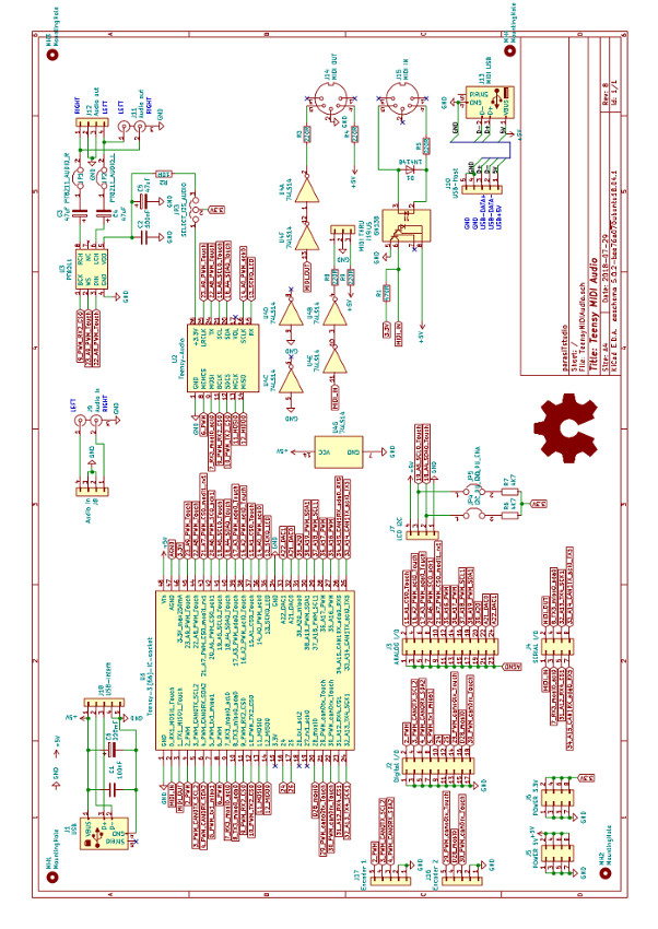
Appendix
Circuit diagram